The r angle (radius) of most PLUS MINUS ZERO (0) products is 2.5mm. One of the reasons is that long ago, the wood was used as it was after the bark was peeled off, and the horns would be shaved off to avoid discomfort during contact. After a long period of time, it will slowly weather and form a rounded corner. In the process of use, the R angle is naturally formed. Its roundness is not an accurate 2.5R, but 2.5R is very close to the natural R angle. Another reason is that when plastic molds are popular, the maximum radial thickness of the shell is 2.5mm, and the maximum R angle is 2.5R. That is to say, 2.5R is a familiar radian, and the edge is the natural radian of wood, which is an inevitable size from the perspective of function and mold processing. If the R angle is larger, it will become a kind of decoration, and the designer's intention will become the pursuit form, which is why I don't want to use a larger R angle.
-"Naoto Fukasawa"
What does Naoto Fukasawa's 2.5R mean?
In essence, 2.5R is the subjective choice of the designer, and at the same time gives it a set of explanations. The designer tells a story that can be justified, puts forward a point of view, and fully explains it. The logic of the whole story is self-consistent. In terms of design, Naoto Fukasawa's 2.5R is an excellent choice, and the two reasons given are also excellent.
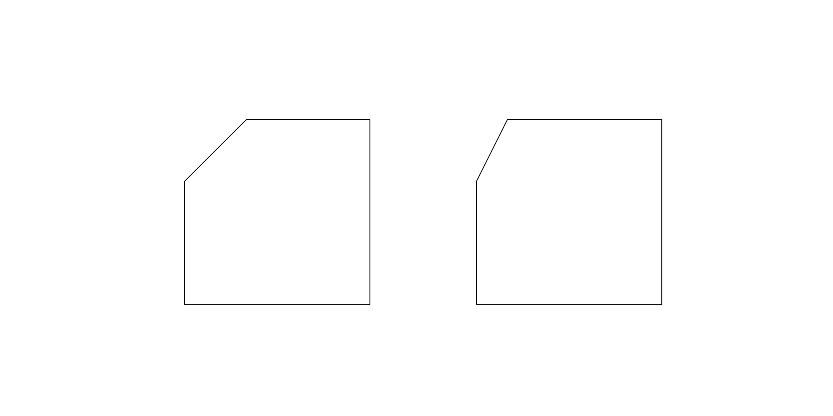
The first reason comes from the designer's long-term deliberate observation. This kind of observation has been internalized into the designer's habit. It does not need to be reminded all the time, but like breathing, observing everything that enters the field of vision, as well as the processing and integration of input information matching the observation. The second reason is extremely wonderful. He used the critical value of plastic material thickness -2.5r. The simple explanation is that we draw a rectangle with a chamfer of 2.5R, and then shift the rectangle inward by 2.5mm on one side. We will get a new rectangle, and the chamfer of this rectangle just disappears.
Why is the offset distance 2.5mm? Because 2.5mm is the universal material thickness of plastic.
Why is the thickness of plastic 2.5mm? This is an experience value. Different types of plastics have different material thicknesses. For example, the material thickness of PP is between 2.3 and 2.5, and that of ABS is between 2.0 and 2.2. From the perspective of injection molding, the thickness of plastic material is ideal between 2.0 and 2.5, and both strength and shrinkage can be taken into account. Therefore, the thickness of plastic is generally about 2.5mm.
When the outer chamfer of the plastic is 2.5R, the thickness of each point of the plastic can be guaranteed to be equal to 2.5mm, even at the corner position. Imagine if the outer chamfer is less than 2.5R, for example, we assume that the chamfer becomes 1mm, then the thickness of the plastic material will suddenly become 4mm at the corner. The increase in local material thickness will make the shrinkage of this point different from other positions, and it is easy to leave traces on the molded plastic surface.
If the outer chamfer is greater than 2.5R, for example, it becomes 3mm, in order to ensure that the shrinkage of the plastic is the same everywhere-because the material thickness is 2.5mm constant-the result is that the inner chamfer of the plastic becomes 0.5mm. There is a question here, why is the thickness of the inner plastic material 0.5mm? Is it the designer's personal choice or personal preference? Is the chamfer of 1.5mm also acceptable? What about 3.0mm? This reason is not convincing enough and will fall into endless debate. And there is another question, is this chamfer part of the decoration?
Therefore, the wonderful thing about 2.5R is that it does not start from the designer's personal preference to tell a story and explain it-although this is actually the designer's personal preference in itself-but from the life experience and the production standards of plastic molds to make a reasonable explanation and justify it.
So, if only from the point of view of skill, chamfering can be divided into which categories?
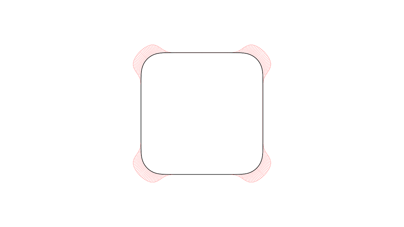
Of course, the first thing that comes to mind is fillet, which is our most intuitive reaction. It is also widely used in design. It is not difficult for us to find out the details of fillet when we pick up a product around us.
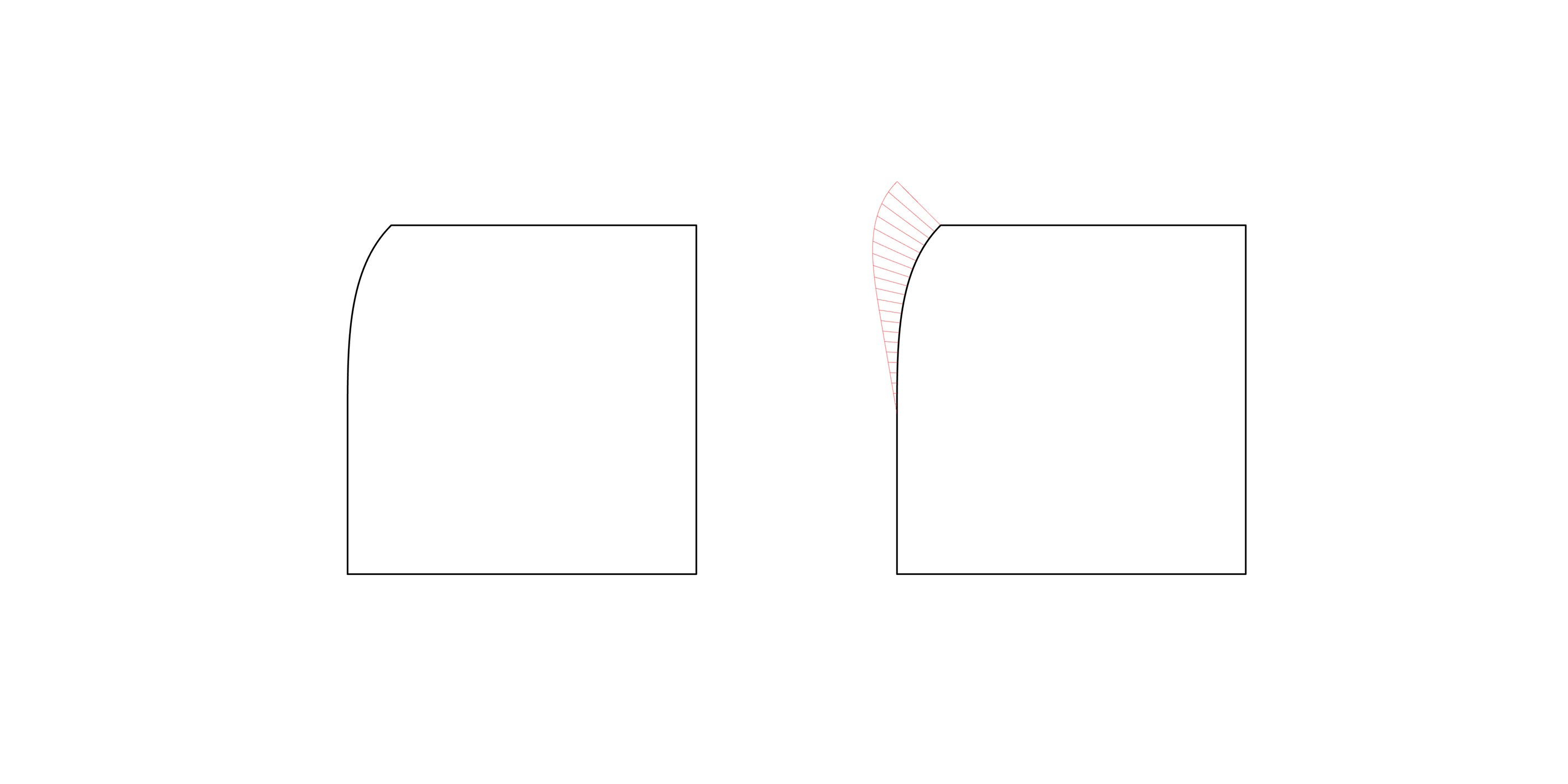
It is composed of two straight lines and a 1/4 arc. The curvature of the straight line is 0, and the curvature of the arc is a fixed value, so although the arc and the straight line are tangent, when applied to the product and carefully observing the tangent point, we can feel that the surface of the product has a tendency to concave at this position. When the highlight hits the tangent point, this feeling will be more obvious. This is because the connection between the straight line and the arc is tangent continuous.
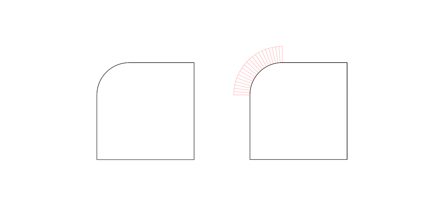
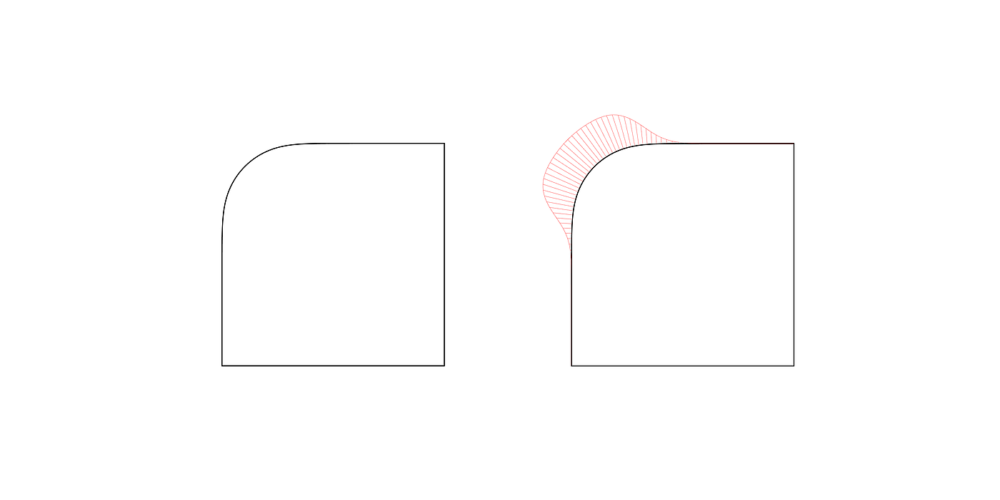
Is there any way to improve it? Yes. We make some changes to the arc of the tangent line, so that the curvature of the two ends gradually increases from 0, that is, the straight line and the fillet are continuous in curvature. Such rounded corners look too smooth. But the direct curvature of the continuous fillet, compared with the tangent continuous chamfer, does not seem to be "round" enough. Therefore, the rounded corners with continuous curvature need to be adjusted more to make them both smooth and smooth. Apple's products use this kind of curve chamfer, but the iPhone's fillet processing is more complicated and fine.
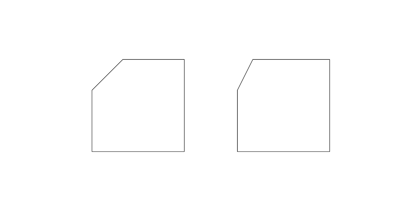
There is also a chamfer called an oblique angle (chamfer), that is, between two straight lines, connected by a diagonal line. Many mobile phones use this chamfering method for the high-gloss edges of the middle frame.
When drawing an oblique angle, we usually set the angle of this oblique line at 45 without thinking. This decision is so rapid that we do not realize that there are other angles to the oblique angle. Before making the oblique angle, we might as well think about whether there are other oblique angles besides the oblique angle of 45 °. Is the oblique angle of 30 ° more suitable? What about the oblique angle of 60 °?
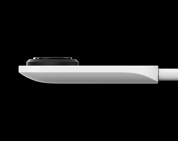
The last treatment of chamfering is to combine fillet and bevel, that is, the connection method with one side is fillet, and the connection method with the other side is bevel. Such chamfers are often used on the edge of a larger plane. It can avoid the abrupt feeling of the plane suddenly disappearing at the boundary, and can make the plane appear to have tension. For example, the aluminum alloy shell of MacBook Air.
This is only an analysis of the types of chamfers from the perspective of design techniques, not that complex chamfers are necessarily good. In the actual design process, it is still necessary to choose the most suitable chamfer. After all, all good designs are first because it is good, and then we analyze that it uses curvature chamfering, golden section, spiral and other techniques, instead of we can pile up a good design with a bunch of techniques.
-------------------------------------------------------------------------------------------------------------------
The old article was reissued, which was written in 2017. At that time, I was curious about chamfering, so I did some sorting. This time, the modeling of curvature fillet was optimized, referring to the modeling idea of "Chen Xian Industrial Design". Thank you for sharing!
References:
Naoto Shenze, "Naoto Shenze", Zhejiang People's Publishing House, 2016
Hi-iD, from rounded to rounded, iD commune
Chen Xian Industrial Design, Constructing Curvature/G3 Fillet from Polygon, Universal Image Net


You offset the square chamfer guide radius 5.2 inward by 5.2mm, which is square
The boss found a story for the 2.5R angle. It is really unnecessary for you to make academic argumentation for the story. It is easy to mislead the novice. not to mention that the material thickness will change due to the product size. As far as most designers are concerned, the work should rarely touch products with 2.5 material thickness.
The plastic wall thickness is determined by the size of the product, not fixed. The wall thickness of the large products we make is 4-5mm. There is also a foaming process to achieve a local thickness of 25mm.
For the structural model sent, the plastic wall thickness is generally 2.1 or 2.2mm. When calculating the cost, the boss also asked how many grams of plastic was used...
Similar to the shell extraction inside creo, the outer guide r angle, r angle is less than the wall thickness of the shell extraction, will fail, suitable for the kind of sheet metal, bending, hot bending products
My head itches. I feel like I'm going to have a brain.
666
Thank you for sharing
Not bad
In the case of different product sizes and target styles, will the fixed use of 2.5R between faces (between two connected faces) cause deviation from the product feeling we originally expected?